I recently purchased an Apple mouse prototype (dated
12/NOV/1980) which was sold by earlyapple (the Huston
brothers) on eBay. I really wanted to bid on it and win the
auction as such an item is rare and is part of the
microcomputer history. I invite you to discover that
prototype with me.
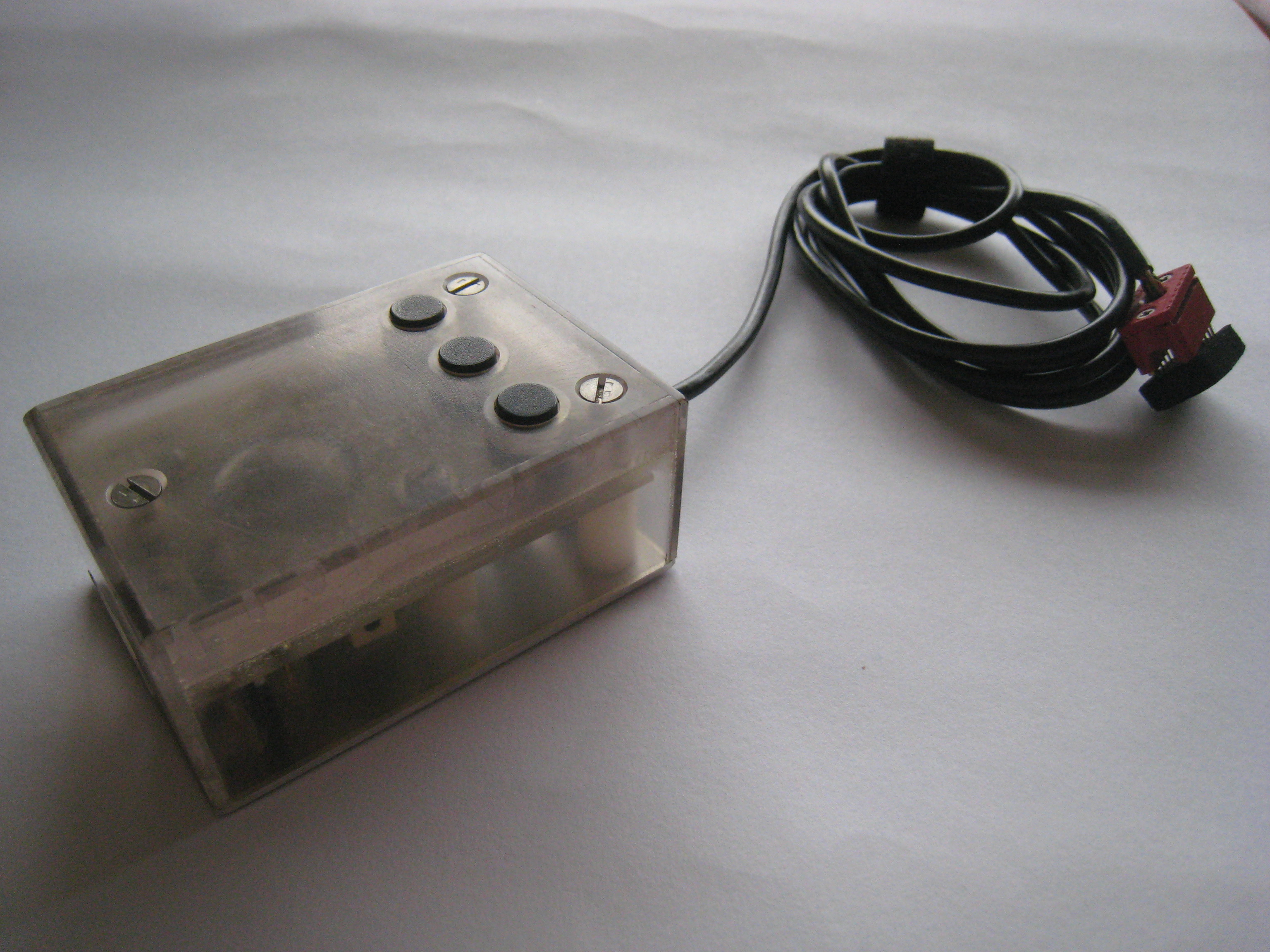
Dimensions
- Length: 80 mm
- Width: 58 mm
- Height: 35 mm
The weight of the beast is unknown but it is heavy. It has three buttons. At the end of the cable, the 16-pins connector plugs into o Apple II's internal 16-pin DIP game connector.
External pictures
Front view
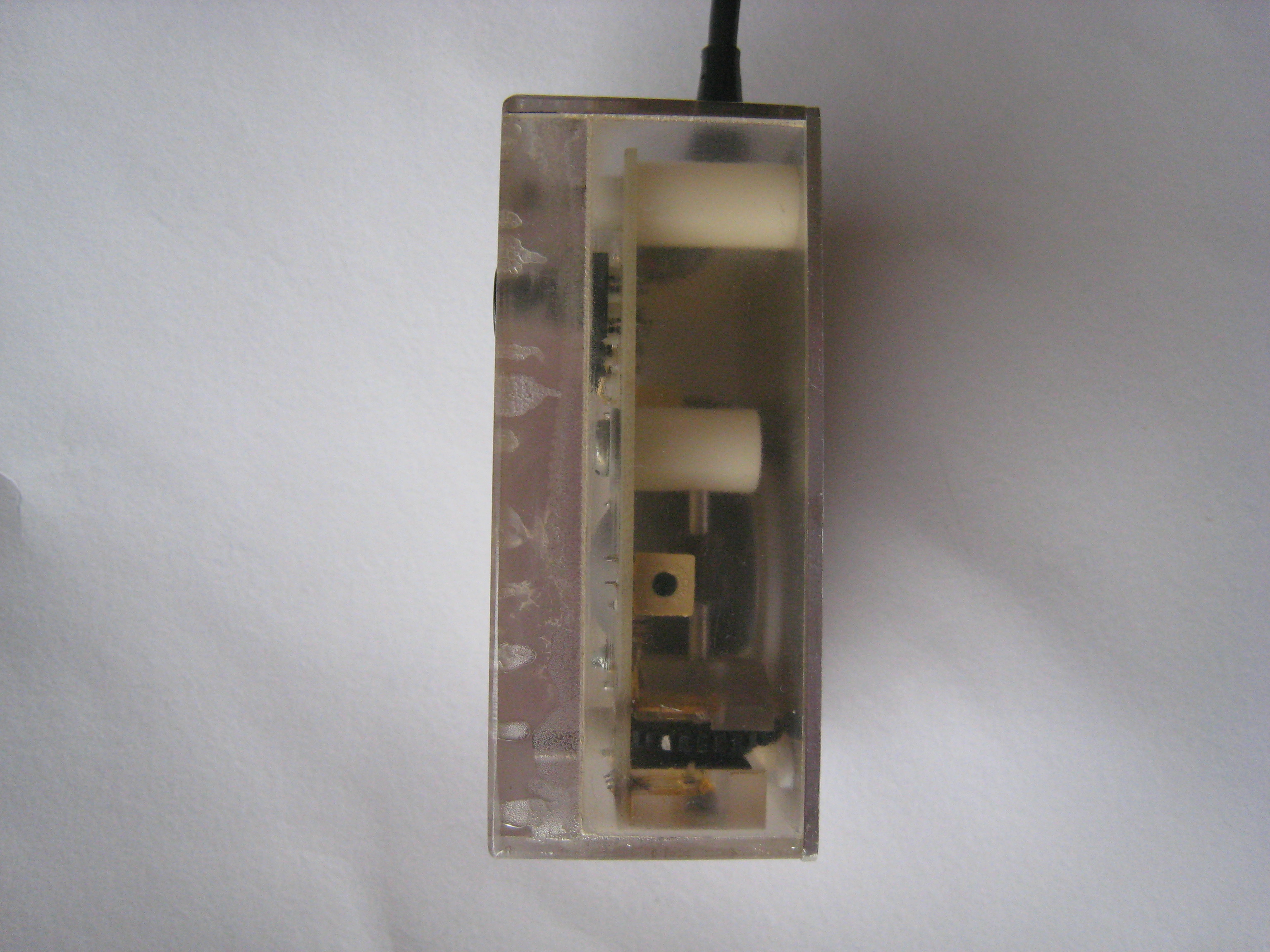
Right view
Back view
Left view
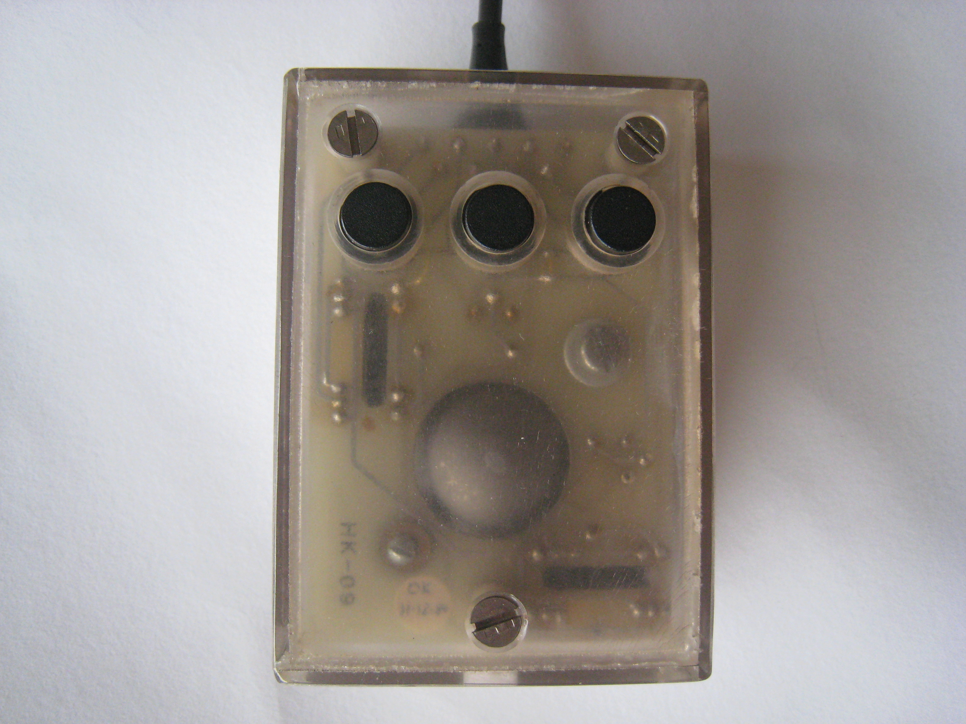
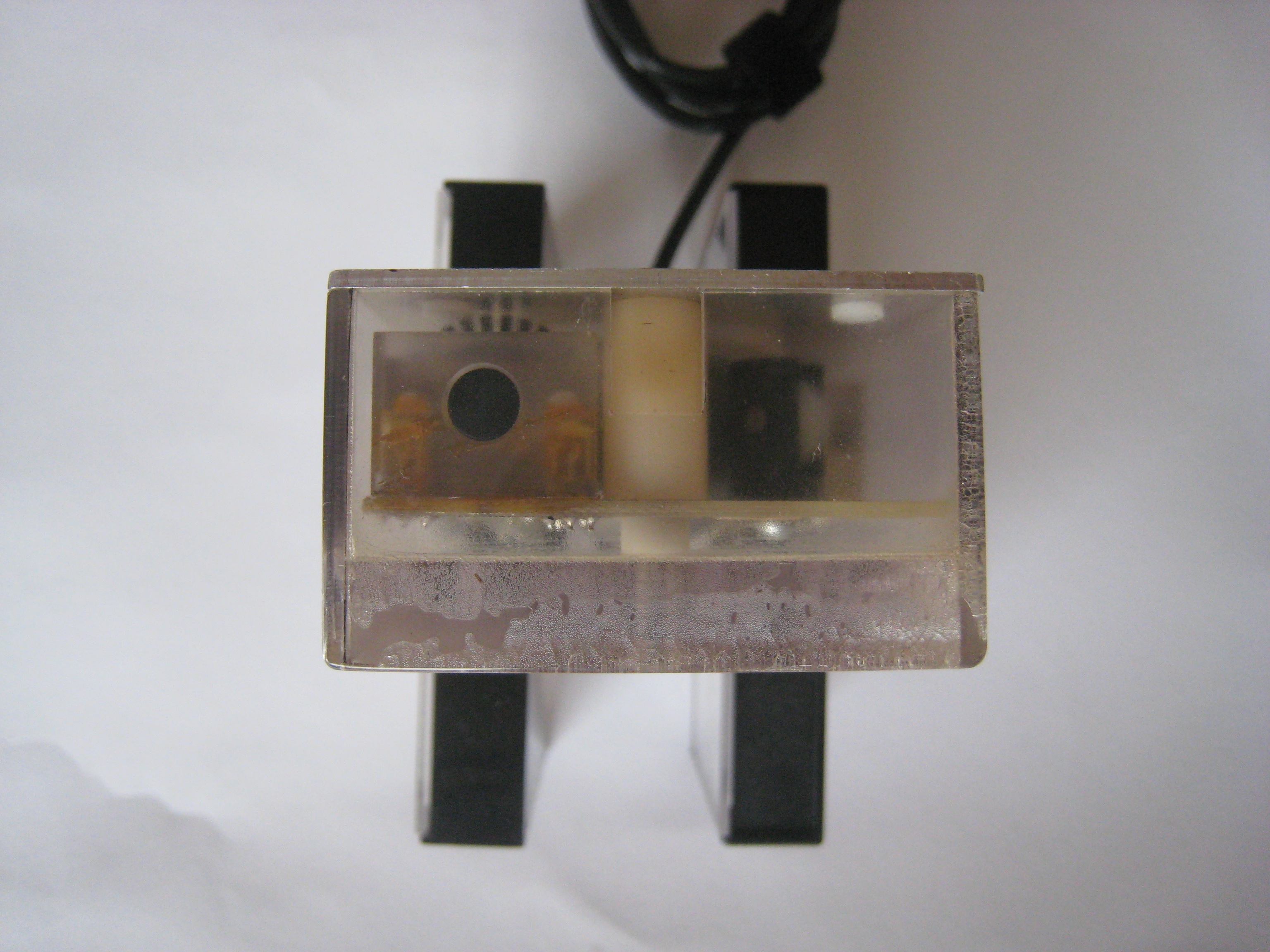
Upper view
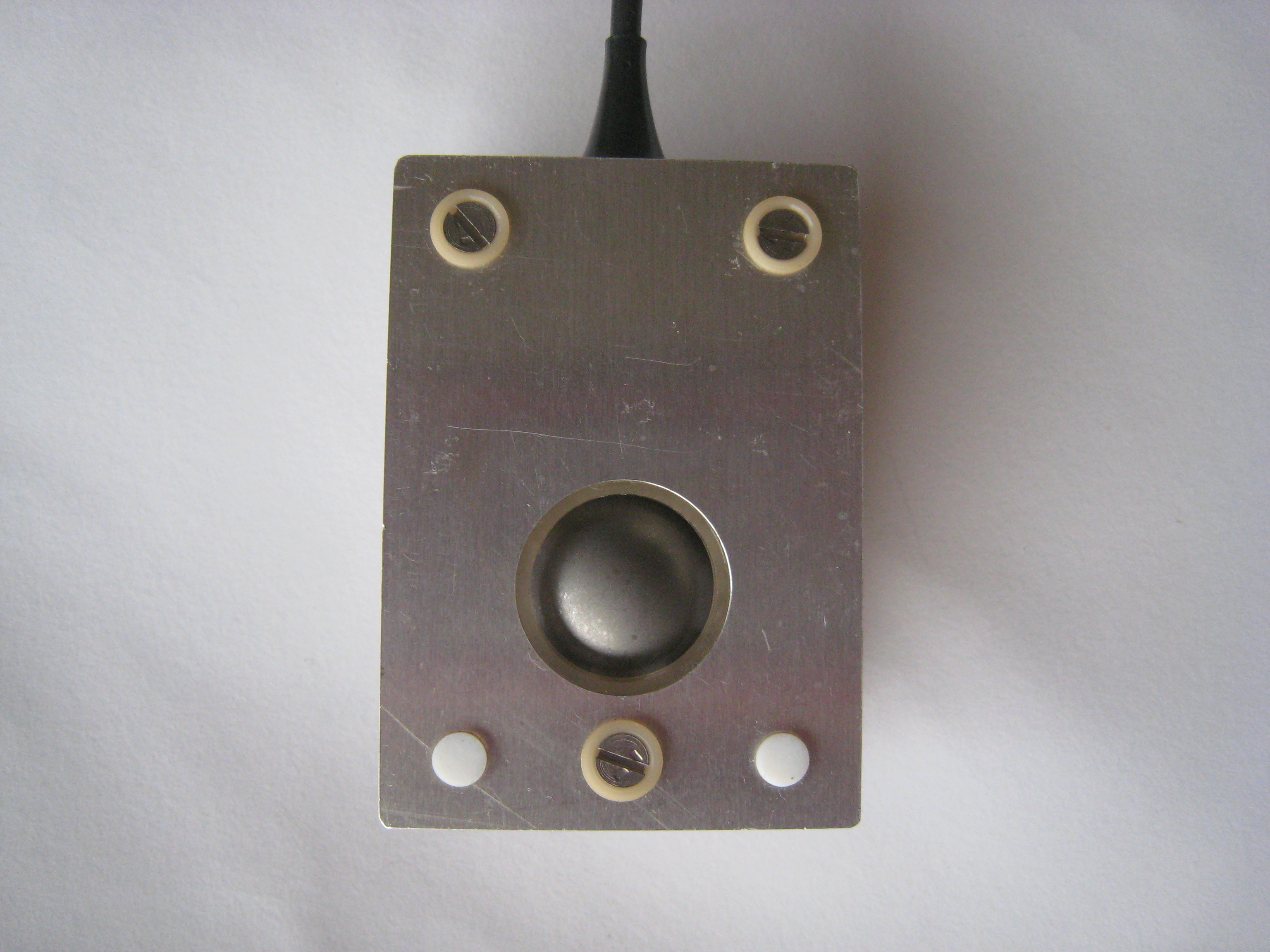
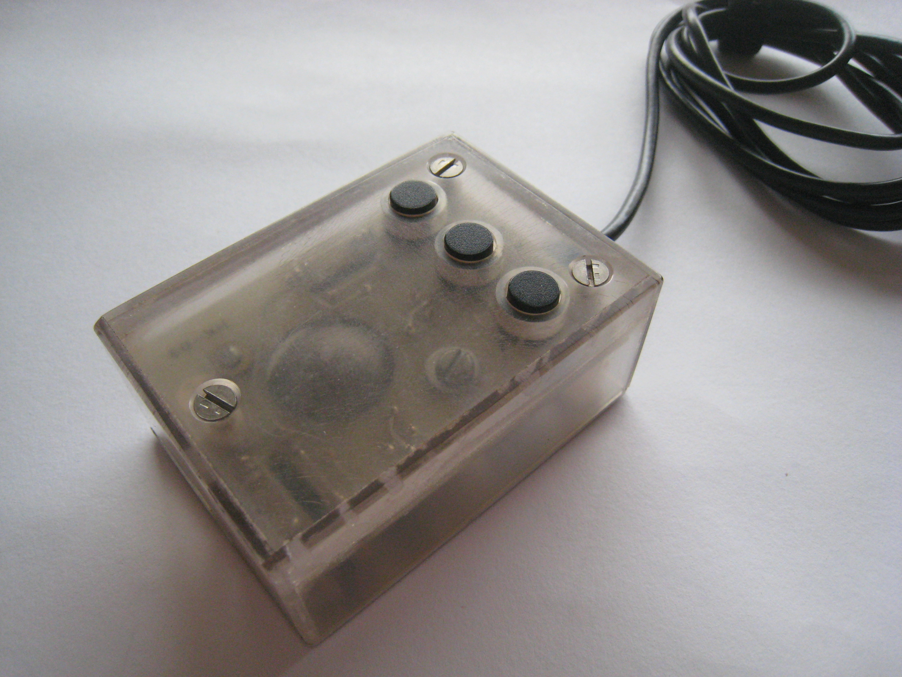
Bottom view
Complete view
Close view
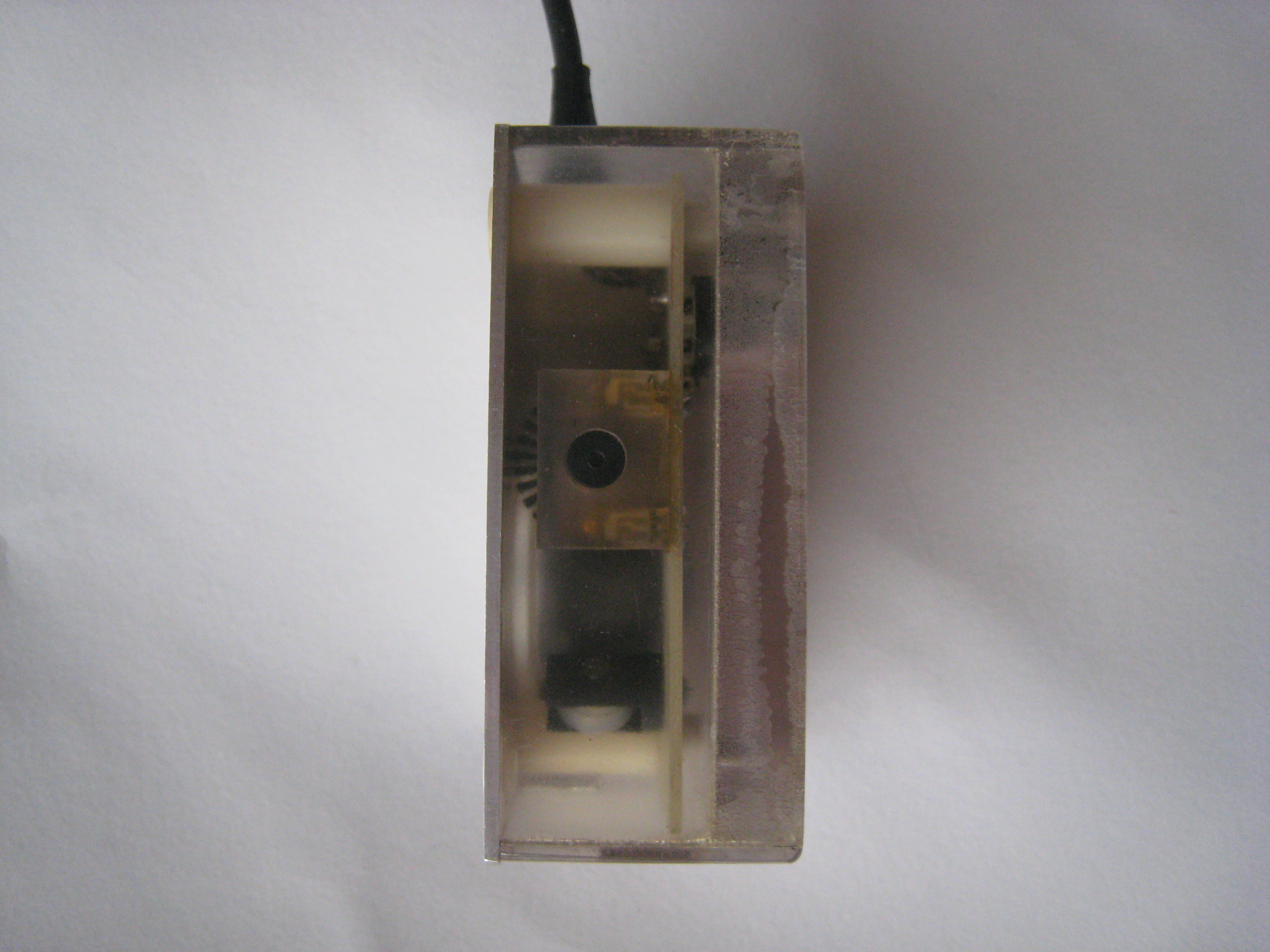
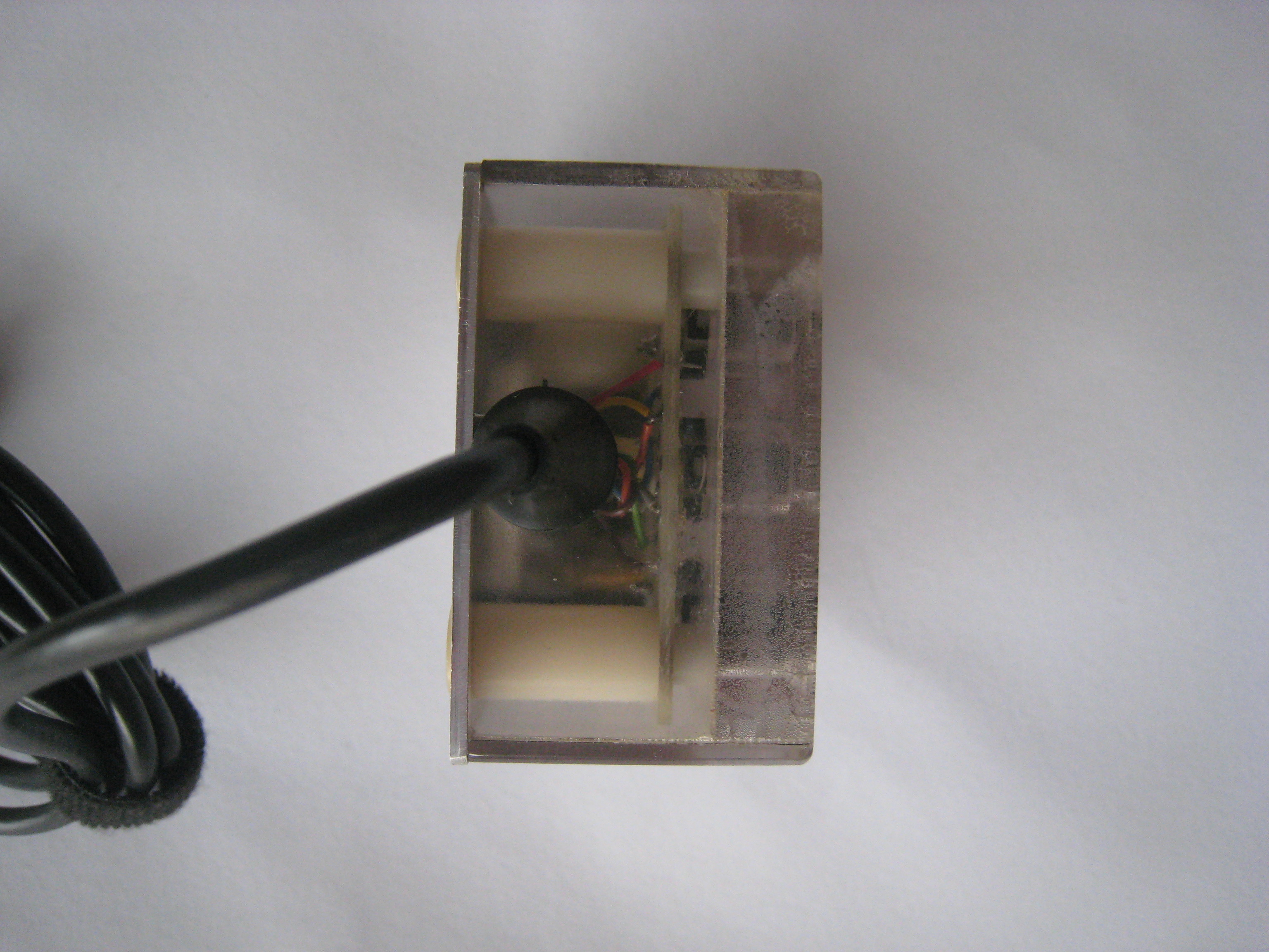
Internal pictures
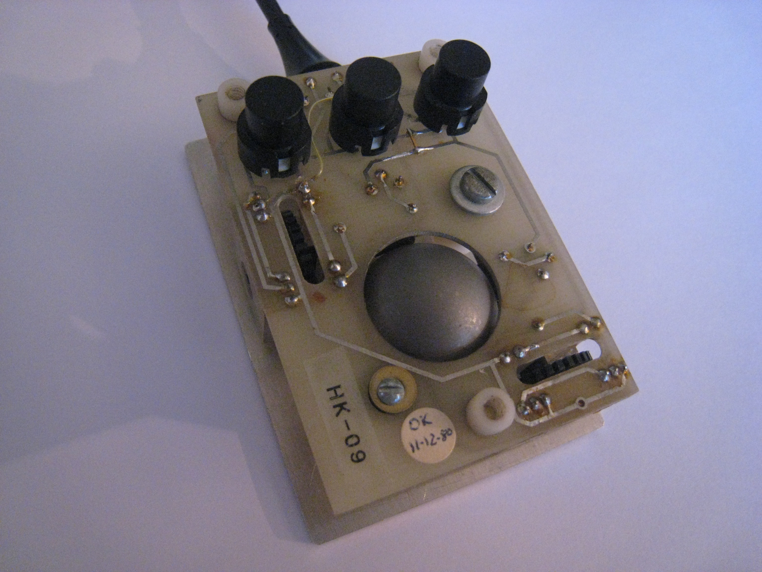
Front view
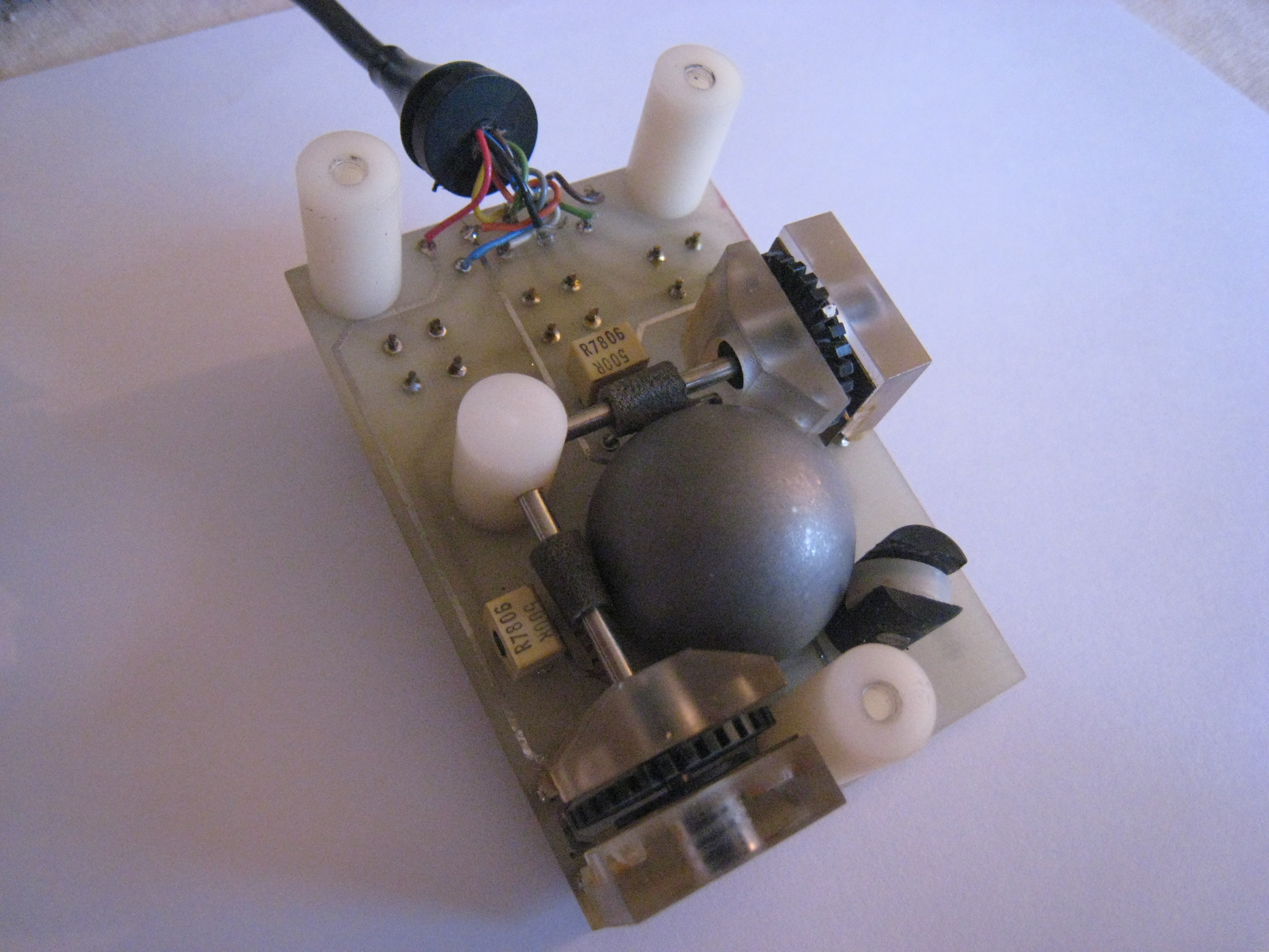
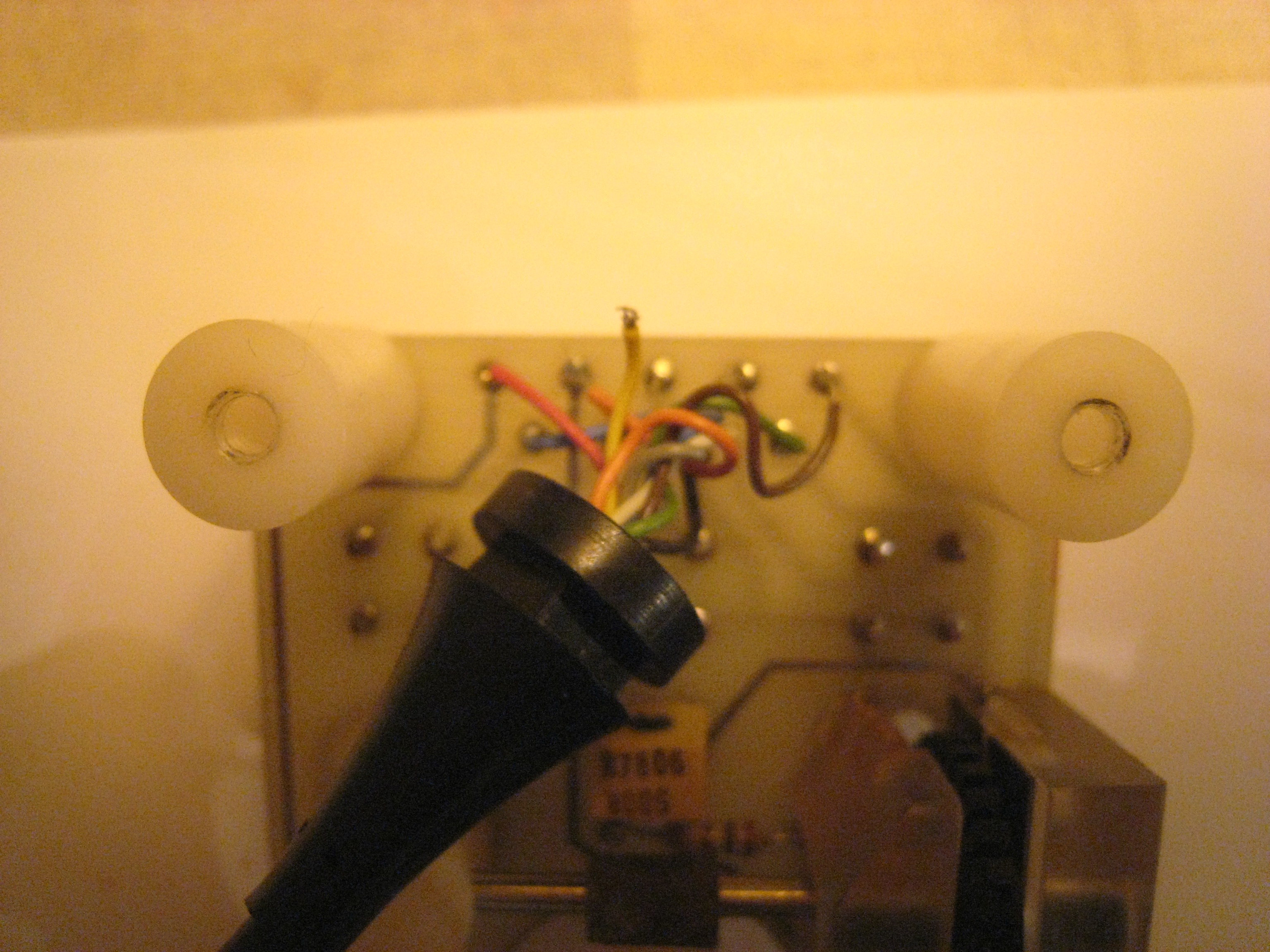
Back view
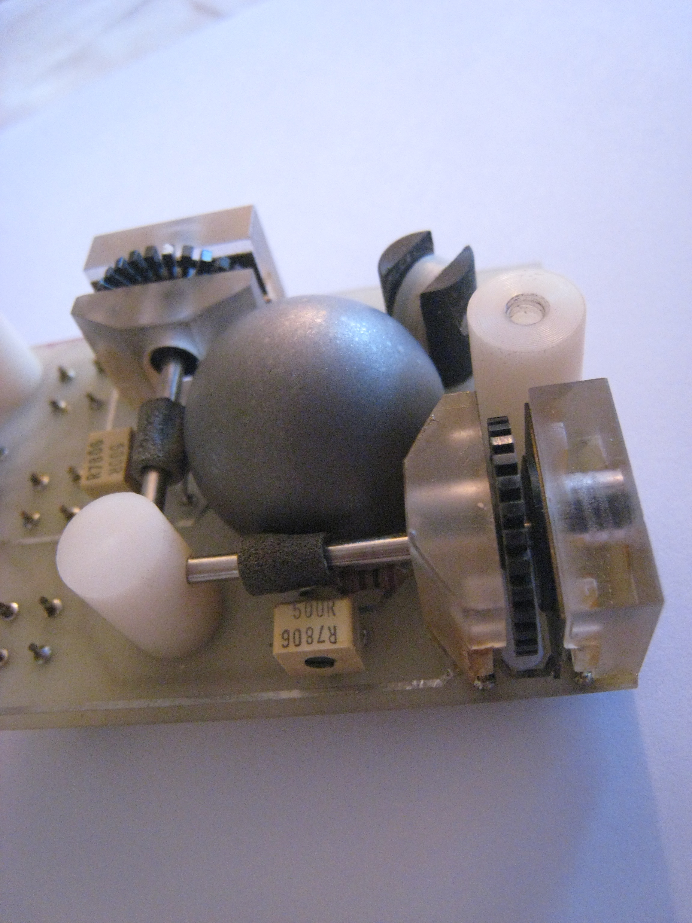
Close view
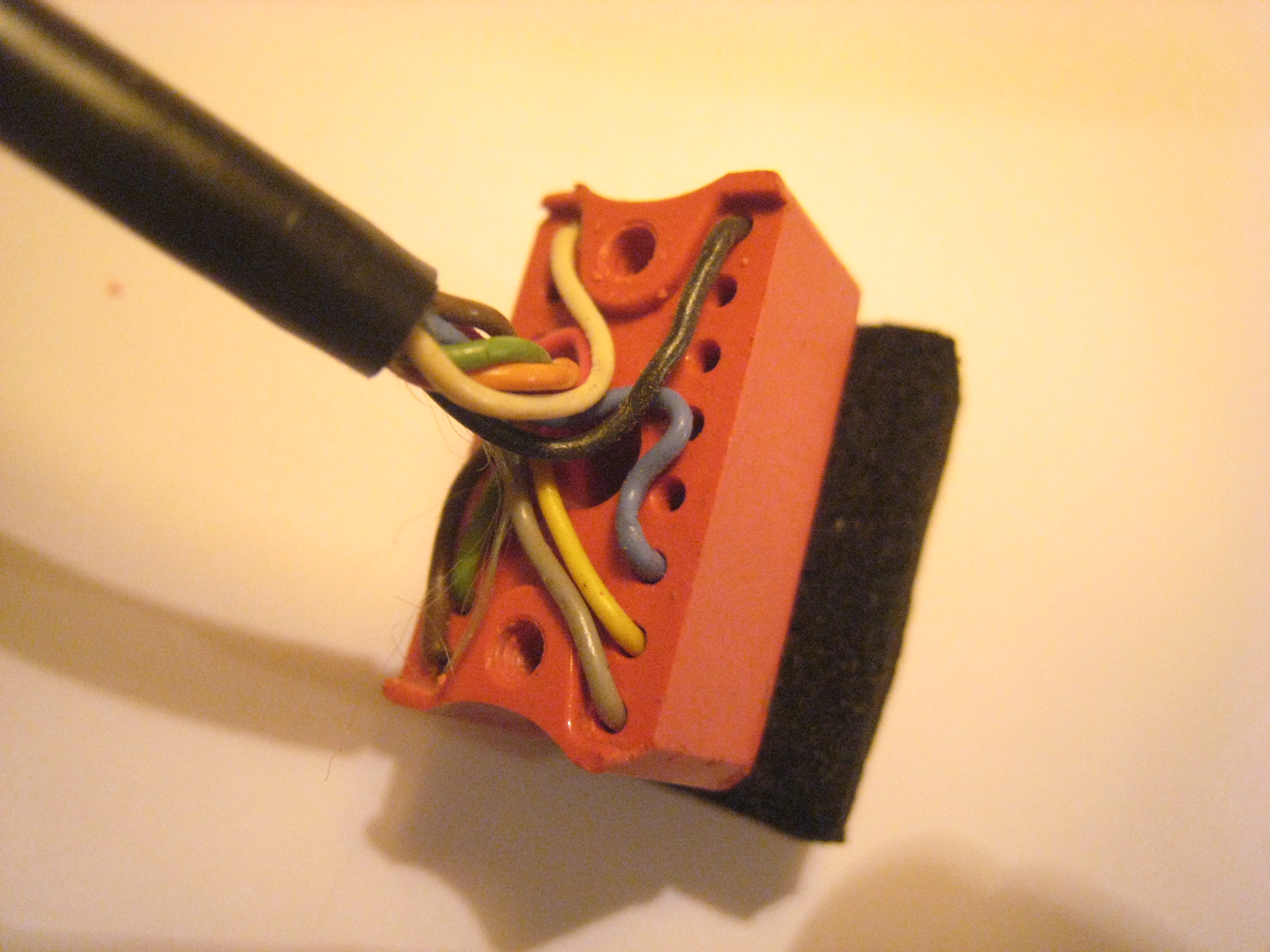
Cable pictures
Connector view
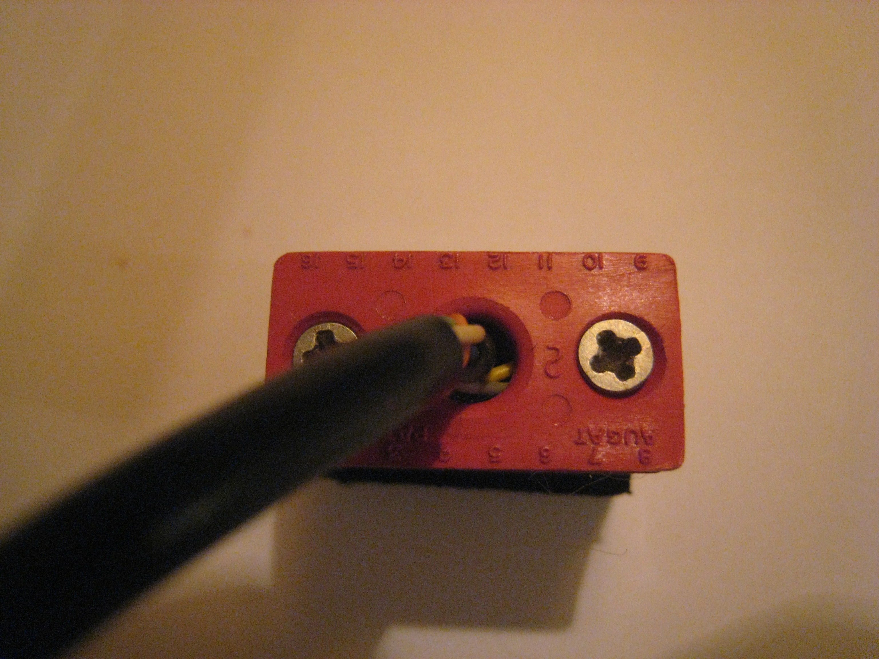
Connector view
Wire view
The mouse and the game I/O signals
Pin number
J21  SIGNAL  WIRE    DESCRIPTION
 1   +5V     white   +5 volts
 2   SW0     n/c     Switch input 0
 3   SW1     n/c     Switch input 1
 4   SW2     n/c     Switch input 2
 5   +5V     red     +5-volt pull-up
 6   PDL0    orange  Analog input 0
 7   PDL2    green   Analog input 2
 8   GND     brown   Power and signal ground
 9   SW3     grey    Switch input 3
10   PDL1    yellow  Analog input 1
11   PDL3    blue    Analog input 3
12   AN3     n/c     Digital output 3
13   AN2     n/c     Digital output 2
14   AN1     n/c     Digital output 1
15   AN0     n/c     Digital output 0
16   N.C.    black   No connection
Let's now study (thanks to the above pictures) which wire does what?
ITEM         WIRE    SIGNAL
wheel U/D    green   PDL2
wheel L/R    orange  PDL0
button 1     grey    SW3
button 2     yellow  PDL1
button 3     blue    PDL3
Eh! It cannot work! There are two wires that are wrongly connected: the state of buttons 2 and 3 cannot be read through PDL1 (10) and PDL3 (11) but, on the contrary, should have been connected to SW0 (2) and SW1 (3). The correct (normal) table should be seen as:
Pin number
J21  SIGNAL  WIRE    DESCRIPTION
 1   +5V     white   +5 volts
 2   SW0     yellow  Switch input 0
 3   SW1     blue    Switch input 1
 4   SW2     n/c     Switch input 2
 5   +5V     red     +5-volt pull-up
 6   PDL0    orange  Analog input 0
 7   PDL2    green   Analog input 2
 8   GND     brown   Power and signal ground
 9   SW3     grey    Switch input 3
10   PDL1    n/c     Analog input 1
11   PDL3    n/c     Analog input 3
12   AN3     n/c     Digital output 3
13   AN2     n/c     Digital output 2
14   AN1     n/c     Digital output 1
15   AN0     n/c     Digital output 0
16   N.C.    black   No connection
And, by feature:
ITEM         WIRE    SIGNAL
wheel U/D    green   PDL2
wheel L/R    orange  PDL0
button 1     grey    SW3
button 2     yellow  SW0
button 3     blue    SW1
I need some advice, how can I move the two pins from pins 10 and 11 to pins 2 and 3 w/o breaking them????????
Testing the mouse
The following Applesoft program can be used to get the
different states from the mouse. What I have not been able
to figure out is how to calculate the mouse movements.
PDL(0) and PDL(2) return a value above 127 if the mouse
moves but it does not say in which direction! Annoying,
isn't it?
10 HOME
20 HTAB 1 : VTAB 1
30 PRINT PDL(0), PDL(2)
40 HTAB 1 : VTAB 3
50 PRINT PEEK(49248), PEEK(49249), PEEK(49250)
60 GOTO 20
You know what, I like my mouse!
Antoine, 7/2010